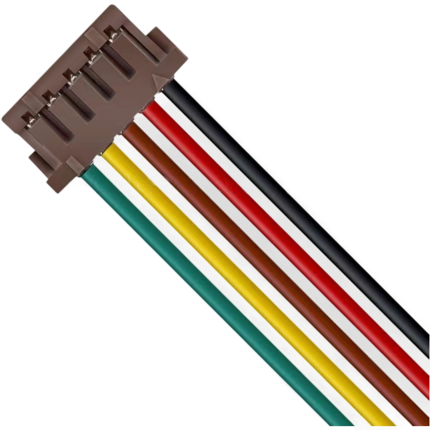
HRS DF13 Series Connector Models and Cable Assembly Specifications
The HRS / Hirose DF13 Series is a compact 1.25 mm pitch connector system for discrete wire connections.
It supports single-row and double-row configurations, through-hole headers, SMT headers, socket housings,
and crimp contacts. DF13 cable assemblies are commonly used in compact electronic devices, internal signal
harnesses, control boards, display modules, industrial devices, and custom wire harness applications.
This page lists common HRS DF13 Series socket housings, board-side headers, SMT headers, crimp contacts,
and general DF13 cable assembly parameter ranges.
1. Single-Row Socket Housing
DF13-2S-1.25C
DF13-3S-1.25C
DF13-4S-1.25C
DF13-5S-1.25C
DF13-6S-1.25C
DF13-7S-1.25C
DF13-8S-1.25C
DF13-9S-1.25C
DF13-10S-1.25C
DF13-11S-1.25C
DF13-12S-1.25C
DF13-13S-1.25C
DF13-14S-1.25C
DF13-15S-1.25C
2. Double-Row Socket Housing
DF13-10DS-1.25C
DF13-20DS-1.25C
DF13-30DS-1.25C(10)
DF13-40DS-1.25C(10)
3. Single-Row Right Angle Through-Hole Pin Header
DF13-2P-1.25DS(25)
DF13-3P-1.25DS(25)
DF13-4P-1.25DS(25)
DF13-5P-1.25DS(25)
DF13-6P-1.25DS(25)
DF13-7P-1.25DS(25)
DF13-8P-1.25DS(25)
DF13-9P-1.25DS(25)
DF13-10P-1.25DS(25)
DF13-11P-1.25DS(25)
DF13-12P-1.25DS(25)
DF13-14P-1.25DS(25)
DF13-15P-1.25DS(25)
Suffix code (25): tin-plated, tube packaging.
4. Single-Row Straight Through-Hole Pin Header
DF13-2P-1.25DSA(05) / DF13-2P-1.25DSA(25)
DF13-3P-1.25DSA(05) / DF13-3P-1.25DSA(25)
DF13-4P-1.25DSA(05) / DF13-4P-1.25DSA(25)
DF13-5P-1.25DSA(05) / DF13-5P-1.25DSA(25)
DF13-6P-1.25DSA(05) / DF13-6P-1.25DSA(25)
DF13-7P-1.25DSA(05) / DF13-7P-1.25DSA(25)
DF13-8P-1.25DSA(05) / DF13-8P-1.25DSA(25)
DF13-9P-1.25DSA(05) / DF13-9P-1.25DSA(25)
DF13-10P-1.25DSA(05) / DF13-10P-1.25DSA(25)
DF13-11P-1.25DSA(05) / DF13-11P-1.25DSA(25)
DF13-12P-1.25DSA(05) / DF13-12P-1.25DSA(25)
DF13-13P-1.25DSA(05) / DF13-13P-1.25DSA(25)
DF13-14P-1.25DSA(05) / DF13-14P-1.25DSA(25)
DF13-15P-1.25DSA(05) / DF13-15P-1.25DSA(25)
Suffix code (05): tin-plated, bag packaging.
Suffix code (25): tin-plated, tube packaging.
5. Single-Row Straight SMT Pin Header — DF13C
DF13C-2P-1.25V(21) / DF13C-2P-1.25V(51)
DF13C-3P-1.25V(21) / DF13C-3P-1.25V(51)
DF13C-4P-1.25V(21) / DF13C-4P-1.25V(51)
DF13C-5P-1.25V(21) / DF13C-5P-1.25V(51)
DF13C-6P-1.25V(21) / DF13C-6P-1.25V(51)
DF13C-7P-1.25V(21) / DF13C-7P-1.25V(51)
DF13C-8P-1.25V(21) / DF13C-8P-1.25V(51)
DF13C-9P-1.25V(21) / DF13C-9P-1.25V(51)
DF13C-10P-1.25V(21) / DF13C-10P-1.25V(51)
DF13C-11P-1.25V(21) / DF13C-11P-1.25V(51)
DF13C-12P-1.25V(21) / DF13C-12P-1.25V(51)
DF13C-14P-1.25V(21) / DF13C-14P-1.25V(51)
DF13C-15P-1.25V(21) / DF13C-15P-1.25V(51)
Suffix code (21): tin-plated, tape-and-reel packaging.
Suffix code (51): gold-plated, tape-and-reel packaging.
6. Single-Row Right Angle SMT Pin Header — DF13A
DF13A-2P-1.25H(21) / DF13A-2P-1.25H(51)
DF13A-3P-1.25H(21) / DF13A-3P-1.25H(51)
DF13A-4P-1.25H(21) / DF13A-4P-1.25H(51)
DF13A-5P-1.25H(21) / DF13A-5P-1.25H(51)
DF13A-6P-1.25H(21) / DF13A-6P-1.25H(51)
DF13A-7P-1.25H(21) / DF13A-7P-1.25H(51)
DF13A-8P-1.25H(21) / DF13A-8P-1.25H(51)
DF13A-9P-1.25H(21) / DF13A-9P-1.25H(51)
DF13A-10P-1.25H(21) / DF13A-10P-1.25H(51)
DF13A-11P-1.25H(21) / DF13A-11P-1.25H(51)
DF13A-12P-1.25H(21) / DF13A-12P-1.25H(51)
DF13A-14P-1.25H(21) / DF13A-14P-1.25H(51)
DF13A-15P-1.25H(21) / DF13A-15P-1.25H(51)
H: horizontal / right angle mounting.
Suffix code (21): tin-plated.
Suffix code (51): gold-plated.
7. Double-Row Straight SMT Pin Header — DF13EA
DF13EA-10DP-1.25V(22)
DF13EA-10DP-1.25V(52)
DF13EA-20DP-1.25V(22)
DF13EA-20DP-1.25V(52)
DF13EA-30DP-1.25V(22)
DF13EA-30DP-1.25V(52)
DF13EA-40DP-1.25V(52)
8. Crimp Contact Models
DF13-2630SCF
DF13-2630SCF(41)
DF13-2630SCFA(04)
DF13-2630SCFA(05)
DF13-2630SCFA(07)
DF13-2630SCFA(41)
DF13-3032SCF
DF13-3032SCFA
DF13G-2630SCF
DF13G-2630SCFA
DF13 Cable Assembly Parameter Range
| Parameter |
DF13 Series Range |
Description |
| Connector Pitch |
1.25 mm |
Center-to-center contact spacing |
| Number of Rows |
1 to 2 rows |
Single-row or double-row configuration |
| Single-Row Positions |
2 to 15 positions |
Single-row housings include a 13-position option |
| Double-Row Positions |
10, 20, 30, and 40 positions |
Corresponding to 5×2, 10×2, 15×2, and 20×2 layouts |
| Applicable Wire Gauge |
AWG26 to AWG32 |
Approximately 0.035 to 0.145 mm² |
| Wire Insulation Outside Diameter |
Approximately 0.50 to 1.00 mm |
Must be confirmed based on the specific contact and crimping conditions |
| Rated Current |
1.0 to 2.5A per pin |
Depends on the number of positions and wire gauge |
| Rated Voltage |
150V AC/DC |
General HRS specification value |
| UL Rated Voltage |
29.9V AC/DC |
UL specification value listed separately in the official catalog |
| Contact Resistance |
30 mΩ maximum |
Under initial and specified test conditions |
| Insulation Resistance |
500 MΩ minimum |
Tested at 100V DC |
| Withstanding Voltage |
500V AC for 1 minute |
No breakdown or flashover |
| Operating Temperature |
-35°C to +85°C |
Includes temperature rise caused by current flow |
| Operating Humidity |
20% to 80% RH |
Non-condensing |
| Storage Temperature |
-10°C to +60°C |
Long-term storage conditions for unassembled products |
| Storage Humidity |
40% to 70% RH |
Non-condensing |
| Mating Cycle Life |
Tin plating: 30 cycles; gold plating: 50 cycles |
Depends on the contact and header plating |
| Locking Method |
Friction lock / mis-insertion prevention structure |
Not a positive secondary-lock structure |
| Flame Retardant Rating |
UL94 V-0 |
Polyamide housing material |
| Contact Material |
Phosphor bronze |
Tin-plated or gold-plated contacts |
| Certifications |
UL E52653, RoHS2 |
Specific part numbers should be verified separately |
DF13 Custom Cable Assembly Options
| Customization Item |
Available Options |
| Connector End |
DF13 single-row socket housing or DF13 double-row socket housing |
| Board-Side Connector |
Through-hole right angle header, through-hole straight header, SMT straight header, or SMT right angle header |
| Number of Positions |
Single-row: 2 to 15 positions; double-row: 10, 20, 30, and 40 positions |
| Wire Gauge |
AWG26, AWG28, AWG30, and AWG32 |
| Wire Type |
Discrete wire for compact internal electronic cable assemblies |
| Cable Length |
Custom lengths are available, such as 50 mm, 100 mm, 300 mm, 500 mm, 1 m, and other customer-specified lengths |
| Wiring Configuration |
1:1 straight wiring, cross wiring, split wiring, terminal conversion wiring, and custom pin assignments |
| Opposite End Interface |
Stripped wire, tinned wire, terminals, JST, Molex, HRS connectors, Dupont terminals, or other custom interfaces |
| Processing Method |
Crimp termination, wire cutting, stripping, tinning, labeling, and harness assembly |
| Testing |
Continuity test, short-circuit test, wiring sequence test, pull test if required, and visual inspection |
| Packaging |
Individual packaging, bulk bag packaging, label packaging, and customized packaging |
Typical DF13 Cable Assembly Applications
DF13 cable assemblies are suitable for compact internal wiring where a 1.25 mm pitch connector is required.
They are commonly used in display modules, control boards, compact electronic devices, industrial instruments,
office automation equipment, communication devices, and other systems that require reliable fine-pitch discrete wire connections.